Click here to get this post in PDF
Key Takeaways
- Isolation transformers transfer AC power through magnetic coupling rather than a direct conductive path.
- Correct selection requires matching voltage, phase, frequency, load demand, location, and system design.
- They can reduce some noise and ground-loop concerns, but they do not replace grounding, surge protection, or overcurrent protection.
- Professional installation and commissioning are essential because transformer circuits can involve lethal voltage.
Sensitive electrical equipment depends on consistent, clean power. An Isolation transformer can help separate a load from its upstream power source, reduce certain noise problems, and support a safer electrical design when it is properly specified and installed.
For facility managers, electricians, engineers, and equipment owners, the decision involves more than selecting a voltage rating. Load characteristics, grounding method, environment, available space, inrush current, protective devices, and applicable code requirements all affect whether the installation performs as intended.
Why Electrical Isolation Matters
Modern facilities often place sensitive controls near electrically noisy loads. Variable-frequency drives, welders, compressors, large motors, switching power supplies, and contactors can introduce disturbances that contribute to communication errors, unstable readings, audio hum, or unexpected controller resets. For example, a nearby motor starting may cause a control panel to restart if the power distribution system is poorly coordinated.
Electrical isolation creates separation between the source circuit and the equipment circuit. Because the galvanic isolation between a source and load provides no direct conductive path, it can be useful for reducing selected noise paths and managing system reference issues. It should still be treated as one layer in a complete power-quality and electrical-safety plan.
How Isolation Transformers Work
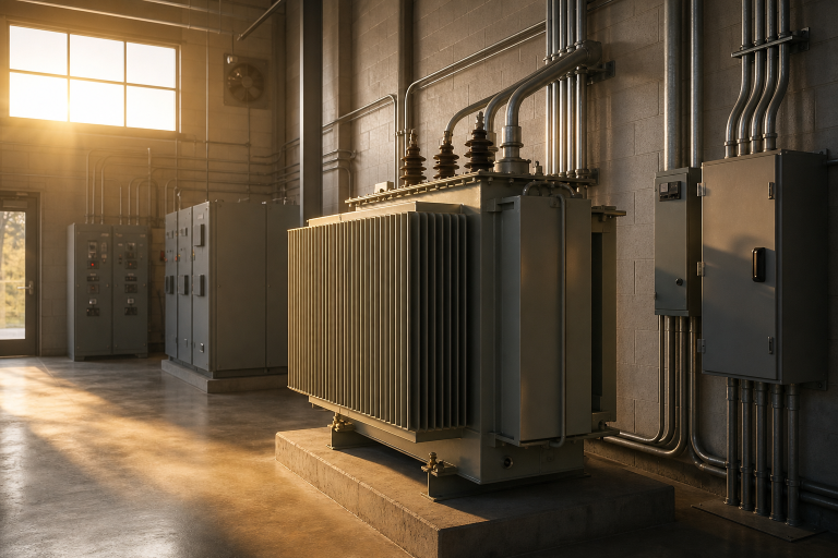
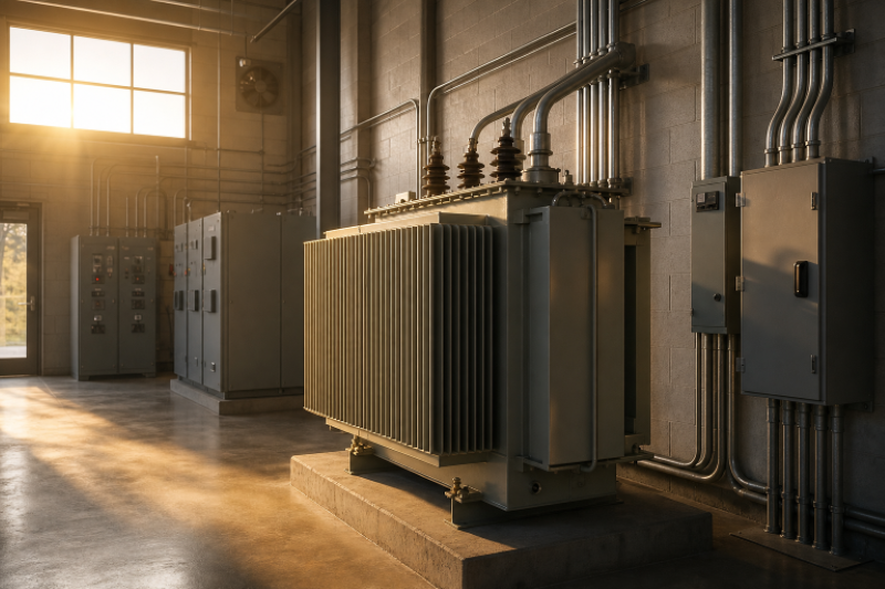
An isolation transformer contains a primary winding, a magnetic core, and a secondary winding. Alternating current in the primary produces a time-varying magnetic field in the core, which induces a voltage in the secondary. Power crosses magnetically, not through a metal connection between the windings.
A one-to-one model typically supplies approximately the same nominal voltage it receives. Step-down models deliver lower output voltage, while step-up models deliver higher output voltage. Some designs include an electrostatic shield between windings. When correctly grounded, that shield can reduce capacitive coupling of common-mode noise. It cannot eliminate every disturbance, especially differential-mode noise, harmonics, or severe surge events.
Isolation also does not make an energized secondary safe to touch. Dangerous voltage can still exist between secondary conductors, so normal guarding, disconnecting, grounding, and lockout procedures remain necessary.
Common Applications
- Industrial controls: Separating PLCs, sensors, and control circuits from noisy motors, drives, and production equipment.
- Data and communications rooms: Supporting stable power distribution for servers, network devices, monitoring hardware, and related controls.
- Medical and laboratory spaces: Helping support specialized designs where leakage current, continuity, accuracy, and fault response are critical.
- Audio and video systems: Reducing hum or interference caused by ground loops between interconnected components.
- Backup and renewable systems: Adding separation within generator, inverter, battery, or mixed-source power arrangements when the overall design calls for it.
Key Selection Factors
Start with the actual electrical system, not the transformer’s physical appearance or price. Confirm the available input voltage at the installation point and the required output voltage for the load. Verify whether the system is single-phase or three-phase, and ensure the unit is rated for the operating frequency, such as 60 Hz in most North American installations.
Next, identify the load type. Heaters are relatively straightforward, whereas motors, pumps, compressors, rectifiers, computers, and variable-speed equipment may exhibit inrush, harmonic, or nonlinear loading characteristics. Also consider enclosure type, heat, dust, moisture, corrosion exposure, restricted access, ventilation needs, and sound limits in offices or occupied areas.
How To Size The Transformer
Transformer capacity is commonly expressed in volt-amperes (VA) or kilovolt-amperes (kVA). List every device the transformer will supply, identify which devices can operate simultaneously, and calculate the expected apparent power. For a single-phase load, VA is generally the product of volts and amps. Three-phase calculations require the appropriate relationship between line voltage and current.
Practical Sizing Steps
- Record the voltage, current, watts, power factor, and duty cycle for each load.
- Add loads that run simultaneously, rather than simply adding every nameplate in the facility.
- Allow for motor starting current and other short-duration demands that may exceed the normal running load.
- Consider the harmonics and heat generated by nonlinear electronic loads.
- Add reasonable spare capacity for planned growth without greatly oversizing the unit.
- Confirm the temperature rise, insulation class, and duty ratings in the equipment documentation.
Installation Planning And Safety
Plan the location before the transformer arrives. The unit needs a stable surface that supports its weight, clear access for inspection, and enough airflow to remove heat. Keep vents unobstructed, route conductors away from damage and heat sources, and leave room for terminations, disconnects, and future service.
Install the required overcurrent protection and disconnecting means in accordance with the approved design. Clearly label the input and output voltages, phases, circuit identification, and emergency disconnect points. Transformer work should be completed by qualified personnel using documented lockout and verification procedures. Electrical wiring requirements for enclosures, conductor protection, and grounding continuity underscore the need for installations to be protected from physical damage and accessible only to appropriate personnel.
Noise, Grounding, And Bonding
Common-mode noise appears between conductors and ground, while differential-mode noise appears between conductors. Isolation transformers may help interrupt or reduce some common-mode pathways, particularly when a grounded electrostatic shield is included. However, sensitive equipment can still receive interference through data cables, communication shields, adjacent wiring, or improperly routed conductors.
Grounding and bonding must follow the electrical system design and local code. Do not assume a secondary neutral should be bonded to ground in every installation, and do not add extra bonding points without engineering review. Unplanned bonds can create circulating current, interference, and unsafe fault behavior. Protective grounding remains necessary even when the power source is isolated.
Mistakes To Avoid
- Sizing only for normal running watts and ignoring inrush current.
- Using a transformer as a substitute for a surge protective device or voltage regulator.
- Failing to verify voltage, phase, frequency, and load compatibility.
- Installing the unit in areas with poor ventilation or limited service access.
- Creating an improper neutral-to-ground bond on the secondary system.
- Protecting power conductors while overlooking noisy data, control, or communication cable paths.
- Skipping commissioning tests after installation or modification.
Maintenance Checklist
Include the transformer in the facility’s preventive maintenance program. Inspect for unusual buzzing, vibration, odor, discoloration, excess heat, loose terminals, damaged insulation, and blocked cooling paths. Record voltage, current, and temperature readings during normal and peak operation. Investigate repeated breaker trips, controller resets, or unexplained equipment faults rather than treating them as routine events.
Periodic infrared scanning under load can help identify hot connections or uneven heating. Keep updated one-line diagrams, test records, torque documentation, and service notes so future technicians understand the transformer’s purpose, secondary grounding arrangement, and connected loads.
Final Guidance
A well-chosen isolation transformer can support cleaner, more stable power for sensitive equipment, but it is not a universal cure for electrical problems. Begin with accurate load data and site conditions, then coordinate transformer selection with grounding, bonding, overcurrent protection, surge protection, cable routing, ventilation, and commissioning. That disciplined approach helps protect equipment performance while improving long-term safety and maintainability.
You may also like:
The Crucial Role of High-Performance Electrical Components and Connectors in Train Applications
Defining Industrial Equipment: From Heavy Machinery to Precision Components